Goal: A DAVE-class DAC I'd actually pay for. From zero FPGA knowledge.
The backstory starts in the 1980s. Music has been my lifeline for as long as I can remember. Headphones have been essential to how I work for as long as I can remember — the ONLY way I can concentrate and get things done is with music on my head. That's been true for 40 years.
The obsession with audio hardware predates this project by decades. In 2002 I was on the Rockbox mailing list — an open-source firmware project for the Archos Jukebox media player — debugging gapless playback, analyzing CBR vs VBR decoding artifacts, and asking about ID3 tag filtering before data hits the decoder chip. Hacking audio player firmware at the hardware level, 23 years before building my own DAC. The thread was always there.
Fast forward to Chord Mojo 1. When I first heard music through that thing, something shifted. Details I'd never perceived before: the squeaking of a piano bench. Someone coughing in the audience. The texture of bows being pulled across cello strings. It wasn't "music listening" anymore — it was "music perceiving." I remember sitting in a client's office, Chord Mojo, Sennheiser IE800, Audirvana feeding Olafur Arnalds in 96kHz. I could hear it all. And I loved it.
I tried other DACs. Bought an RME ADI-2 DAC in Japan alongside a Hifiman HE1000 Unveiled. Great reviews, great specs. Back home... I hated it. Flat. Boring. I tried every filter setting — linear phase, NOS, minimum phase — but I couldn't articulate WHY it was wrong. I just missed "falling into the depth of music." That feeling where reverb creates a three-dimensional space and you're INSIDE it.
Last resort: plugged in my Mojo 2. Magic was back instantly. Mojo 2 → Burson Soloist → Hifiman planars? Transcendent. That confirmed it wasn't placebo. Something about that sound creates what I can only describe as "auditory OLED." Pitch black background. Razor sharp transients. High-contrast sound that makes music feel real.
So naturally: what's the best headphone? Hifiman Susvara. Bought it. Loved it. But then... what's next? More taps = more magic? Then I need more taps. Hugo TT2? $5k. DAVE? $12k+. No. I don't pay $12k for a DAC. I'd rather build my own.
Because: I've been writing software since age 6. Over 40 years. And what's an FPGA? Software-defined hardware. "How hard can it be?"
Famous last words.
starting from zero
Starting from ZERO:
  - Never touched Verilog in my life
  - Never used an oscilloscope
  - Never designed a circuit
  - Never ordered a PCB
  - Never heard of sigma-delta modulation
  - Never implemented a FIR filter
Using AI as my teacher (Claude, specifically — learning the way I learn best: try, fail, ask questions, remember forever), I went into full hyperfocus mode.
Today: 507,904-tap polyphase FIR. 9th-order noise shaper. 20-element pulse array. Custom 8-layer PCB. Audio coming out of an FPGA that sounds like it has no business sounding this good. And now it's becoming a real product — the BELLA DAC 1, under Pretty Good DACs.
format · stack · signal chain
Format: FPGA audio DAC — digital signal processing in Verilog,
analog output stage on custom PCB, MATLAB for algorithm validation.

Stack:
  - Trenz TE0712-03 module (XC7A200T Artix-7) on my own carrier PCB
    (started on a Digilent Nexys Video, Dec 2025)
  - XMOS XU316 front panel: USB audio, 3.5" IPS display, rotary knob
  - Verilog (109 files, ~44,000 lines)
  - Vivado (synthesis + P&R, ~17 min full build)
  - MATLAB (SDM design, bit-exact fixed-point models)
  - Python (coefficient generation, control tool, FFT captures)
  - KiCad (custom PCB, now rev 0.7.2 — 8 layers)
  - 2-stage OPA1612 analog output, LT3045 low-noise rails

Signal chain:
  USB Audio → XMOS → I2S → FPGA:
    volume + 10-band parametric EQ (before the FIR)
    → 64× Polyphase FIR (507,904 taps, 165 ms long)
    → ASRC + cubic interpolation up to 100 MHz
    → 9th-order noise shaper (21 levels, 100 MHz)
    → 20-element pulse array per channel (PAWS)
  → external flip-flops reclock every pin to a clean 100 MHz clock
  → Analog reconstruction (OPA1612)
  → Headphone Amplifier → Susvara
SIGNAL PROCESSINGWhy It Sounds Different
507,904-Tap Polyphase FIR — Transient Reconstruction
This is about reconstructing transients — the sharp attacks and decays that make music feel REAL.
polyphase FIR · 507,904 taps
My implementation: 64× upsampling via polyphase FIR.
  - 124 filter tiles × 32 taps × 64 phases = 253,952 taps (1× mode)
  - 2× mode via symmetric coefficients = 507,904 taps
    (the default — the DAC boots in 2×)
  - Filter length: 165.3 ms at 48 kHz
  - 2 DSP48E1 per tile: 32-bit coefficients split 17 + 15 bits
  - Accumulation inside the DSP's own P register, 64 bits wide
  - 496 DSPs for the FIR alone. Whole chip: ~86% DSP, ~87% BRAM.
  - Custom-designed windows (the "GOAT filter" family)
  - 3 factory voicings: SUSVARA / BASELINE / PRECISION
  - Field-updatable coefficients via UART or USB-C
For context: Chord DAVE uses ~164,000 taps. I'm at 507,904. Over 3× DAVE.
Why 64× and not 256×? The tap budget is fixed by the clock: 4,096 multiplies per tile per input sample. Lower oversampling buys a LONGER filter from the same taps. 256× gave 41 ms. 64× gives 165 ms. I measured where transient accuracy stops improving: about 165 ms. Then I listened. Same answer.
The coefficients are generated in Python and stored in 124 BRAMs per channel. Uploads take seconds. A full build takes ~17 minutes — it took 1 h 53 before I moved the FIR's adding into the DSP blocks themselves. That one change deleted 29% of all flip-flops on the chip.
9th-Order CRFB Sigma-Delta Modulator
The FIR outputs clean, highly oversampled audio. But you can't feed that directly to a 1-bit or few-bit output — you need noise shaping to push quantization noise above the audible band.
sigma-delta modulator · CRFB
My SDM: 9th-order Cascade of Resonators, Feedback Form (CRFB).
  - 21 output levels (-20 to +20, step 2)
  - Runs at 100 MHz
  - Designed with the Schreier Delta-Sigma Toolbox in MATLAB
  - Verilog is bit-exact against the MATLAB model
  - Every multiply fits one DSP48E1 natively (25×18)
The road here: 2nd, 3rd, 4th, then 5th order with 65 levels. Now 9th order with 21 levels. Higher order pushes the noise out of the audio band harder. Fewer levels means fewer elements that have to match each other. The noise shaper is designed in MATLAB first, checked bit-for-bit against the Verilog, and only then built.
This is where I spent months debugging before understanding WHY.
The problem: converting a multi-level SDM output to analog. The naive approach (thermometer encoding — more "on" pins for higher values) has a fatal flaw: SIGNAL-DEPENDENT switching noise. The number of transitions per cycle depends on the signal, which modulates the noise floor. You can hear it as "graininess."
My implementation: PAWS — 20 elements per channel. The switching pattern doesn't depend on the music, so the noise floor doesn't either.
I learned this the hard way. Months of "why does thermometer encoding sound grainy?" until the theory clicked.
The FPGA pins themselves are not clean enough. So every pin goes through an external flip-flop, reclocked from a dedicated 100 MHz crystal, on its own LT3045 low-noise rail. Current board: 0.7.2, 2×20 elements.
Custom PCBs — Learning Hardware From Zero
The FPGA is 50% of the project. The other 50% is getting analog audio out of digital pulse trains. That means: opamps, resistor networks, power supplies, ground planes, impedance matching.
PCB · hardware iteration
In December 2025 I didn't know what KiCad was. Since then: 14 board
revisions, 0.1.1 → 0.7.2. The current one is 8 layers with:
  - Trenz TE0712 FPGA module (Artix-7 200T)
  - 40 flip-flops reclocking the pulse array
  - 3× LT3045 low-noise regulators (flip-flop + clock rails)
  - CDCLVC1103 clock buffer
  - Split analog / digital ground
  - XMOS XU316 front panel, FT232H on USB-C for control
  - 2-stage OPA1612 output
  - Designed for JLCPCB manufacturing (full SMT assembly)
Every board revision ships from Shenzhen. I order, wait 2 weeks, solder, test, learn, iterate. It's the slowest feedback loop in the project — and the most satisfying when it works.
Oh, and I taught myself SMD soldering. Bought a rework station to fix a JLCPCB assembly mistake. In December 2025 I didn't know which end of a soldering iron gets hot. Now I'm reflowing 0603 components with a hot air gun. The speedrun has no brakes.
SCREENSHOTSFrom Zero to DAC
The Hardware in 01–02/2026
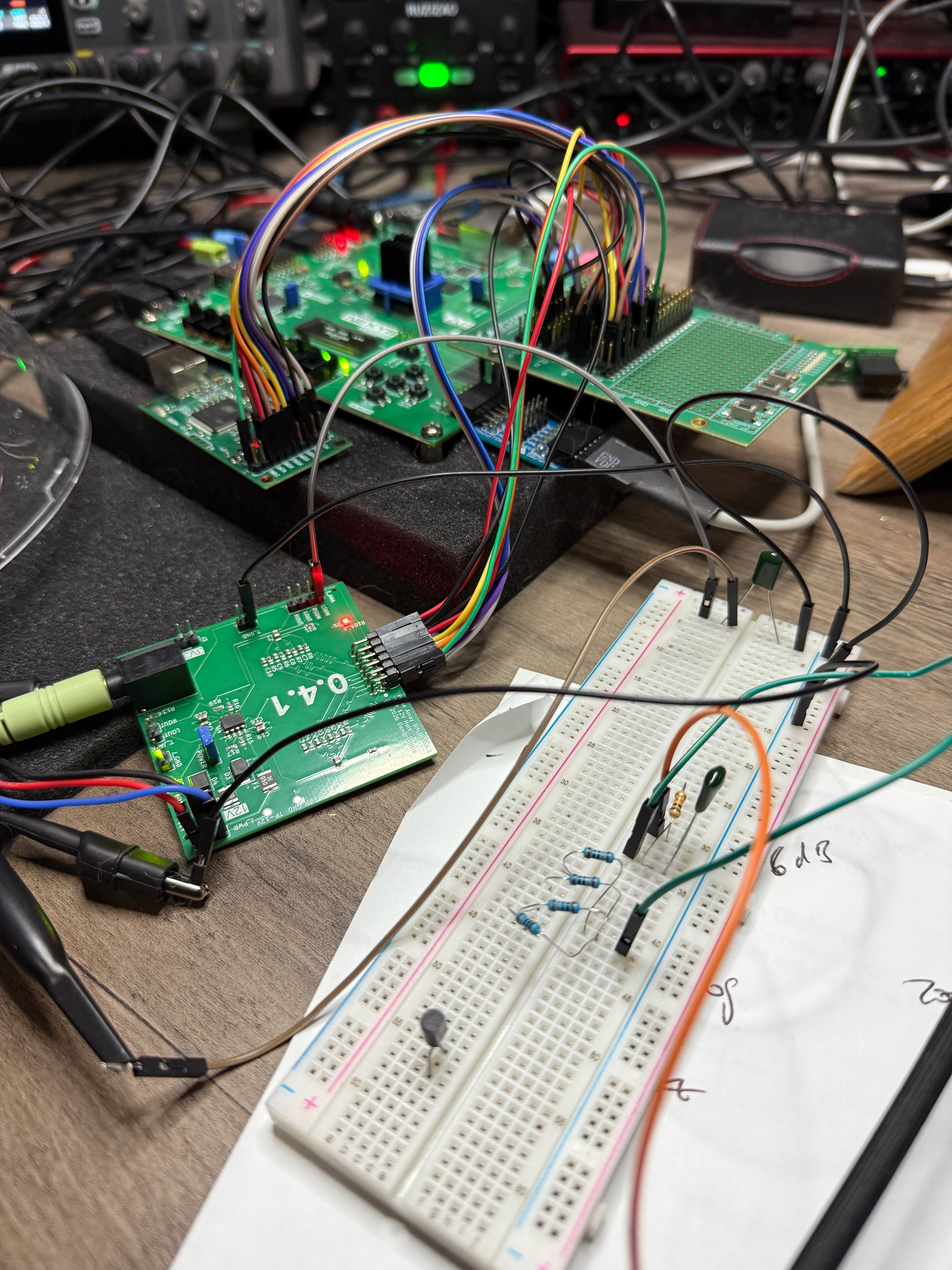
workbench-chaos.jpeg
What FPGA audio engineering actually looks like. Nexys Video board, custom PCB v0.4.1, breadboard analog stage, oscilloscope probes, handwritten notes. Three months ago none of this existed.
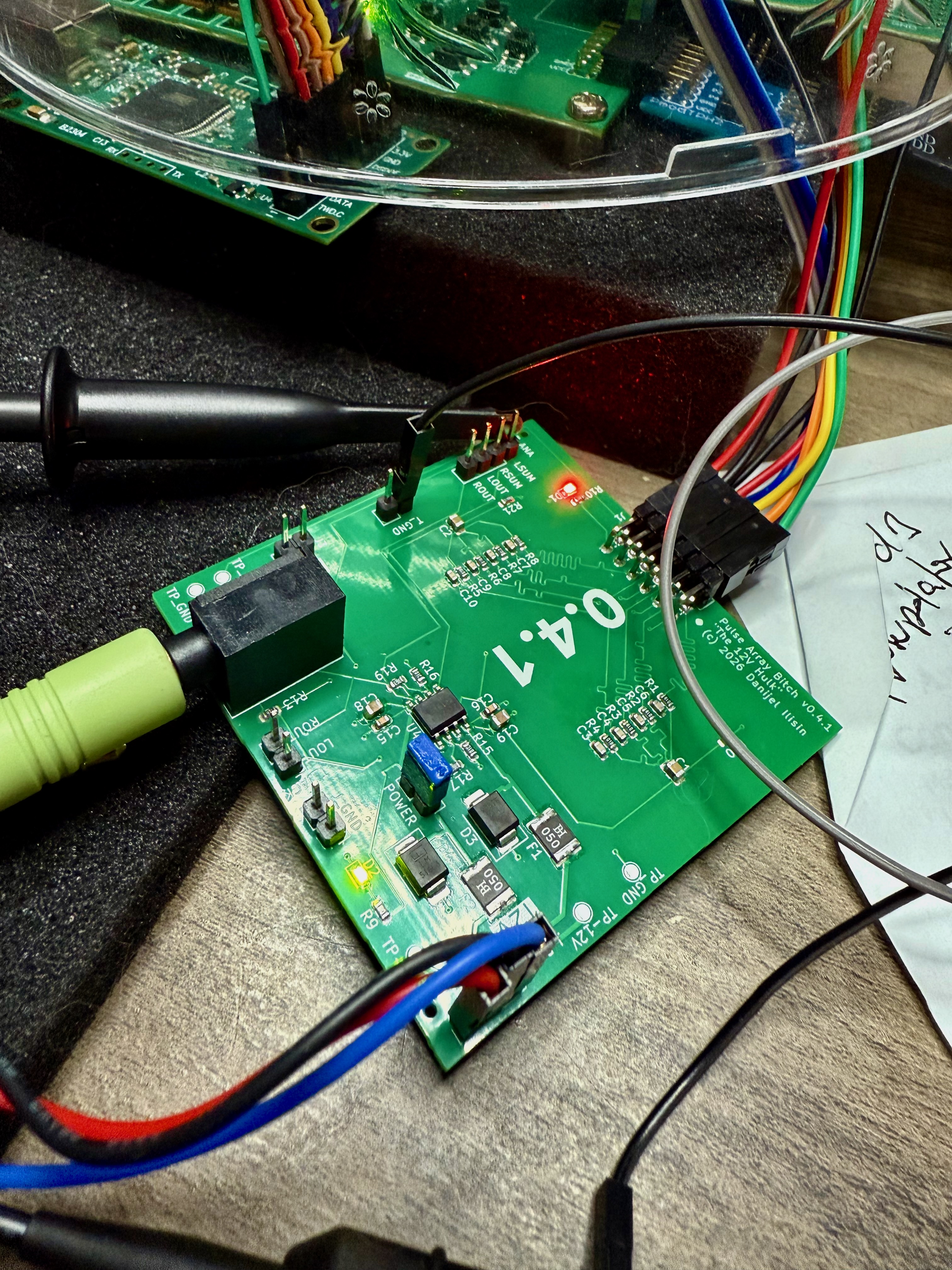
pcb-v041-closeup.jpeg
Custom PCB v0.4.1 — designed in KiCad, manufactured by JLCPCB, probed with a Siglent oscilloscope. That "0.4.1" silkscreen is three months of iteration compressed into a green rectangle.
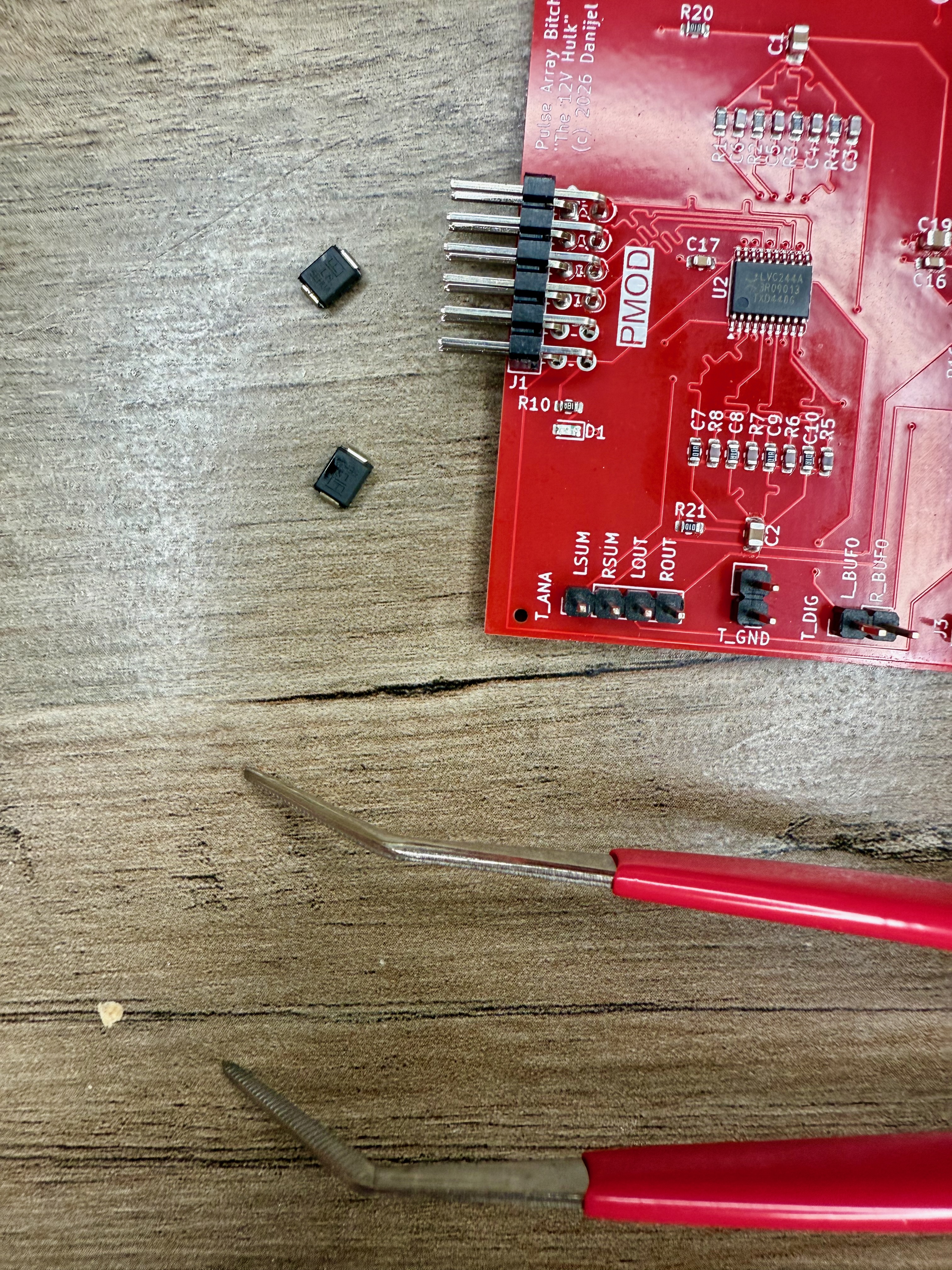
smd-rework-red-pcb.jpeg
Teaching myself SMD soldering to fix a JLCPCB assembly mistake. Tweezers, tiny components, and a rework station I bought specifically for this. The speedrun has no brakes.
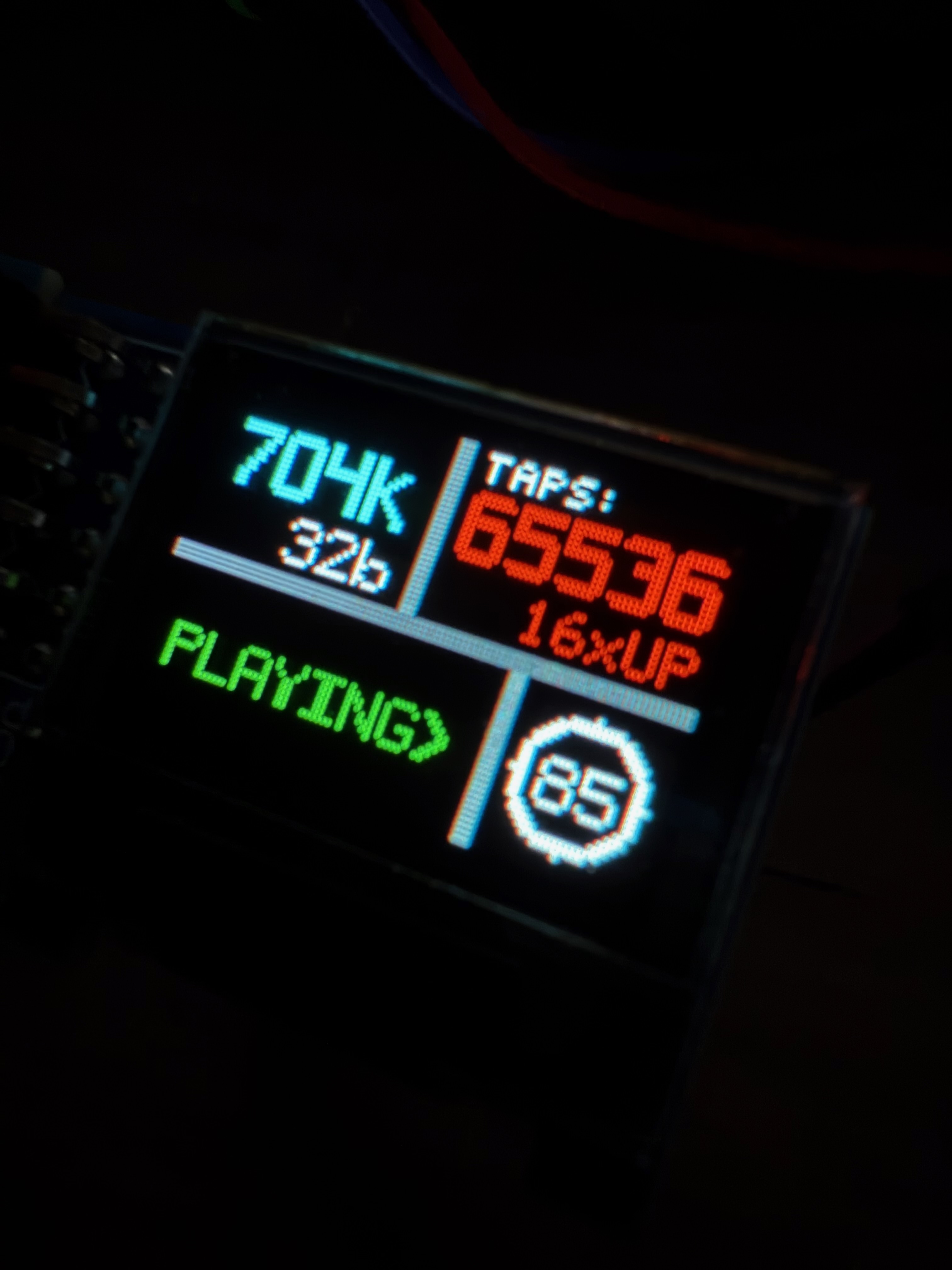
oled-display-playing.jpeg
The OLED display via Digilent PMOD. 704K sample rate, 32-bit, 65,536 taps, 16× upsampling, volume 85. Glowing in the dark like a proper piece of audio gear. Because aesthetics matter.
POSTLearnings · Afterthoughts · Timeline
learnings
What I learned:

  - You can teach yourself FPGA development from zero using AI as
    a tutor. The learning style of try → fail → ask → never forget,
    combined with Claude's patience, is absurdly effective.

  - Filter LENGTH beats oversampling ratio. Same 507,904 taps:
    256× = 41 ms, 64× = 165 ms. Going DOWN in oversampling made
    it better.

  - Build time is routing congestion, not timing slack. Moving the
    FIR accumulation into the DSP blocks cut 29% of all flip-flops.
    Build: 1h53 → 17 min. Same tile count.

  - Static measurements lie. Dither off measured better on every
    steady tone. On a fade-out the noise floor pumped. Test with
    signals that DECAY, not just signals that sit still.

  - Thermometer encoding is a trap. It looks obvious. It's wrong.
    Signal-dependent switching noise is real and audible. I spent
    months learning this. Signal-independent switching or nothing.

  - Custom PCBs from China are magical. A multi-layer board with
    full assembly, delivered in 2 weeks. The
    democratisation of hardware is real.

  - MATLAB is not optional for DSP work. You MUST validate
    algorithms in simulation before translating to Verilog. The
    feedback cycle is too slow otherwise.

  - The audio community responds when you give them a product to
    believe in. The moment I announced "this is becoming a product,"
    engagement exploded. First beta tester within 5 minutes.
The connection to everything else: This project is the same thing as Friend, just in a different domain. Friend reconstructs authentic connection from data. The DAC reconstructs authentic sound from samples. Both are about removing layers of distortion between me and reality. Both are about building what I need because nobody's selling it at a price — or quality — that makes sense.
I've spent my life exploring what's real. If we're living in a simulation (and I half-believe we are), then signal reconstruction is literally how the universe renders experience. A DAC that perfectly reconstructs an analog waveform from digital samples is doing what reality does every time you hear a sound. Understanding that process — truly, at the silicon level — feels like peeking behind the curtain.
what's next
What's next:
  Path chosen: build a product. The BELLA DAC 1 by Pretty Good DACs.
  507,904 taps. 165 ms filter. 20-element pulse array. Field-updatable.
  Not competing with Chord — I genuinely
  respect their products. This is about pushing the limits of
  what's physically possible and seeing how far the philosophy
  scales. prettygooddacs.com is live. Waitlist is open.
timeline · 473 commits in 290 days
Timeline (473 commits in 290 days):
  - 2025-12-15: First commit. "How hard can it be?" — famous last
    words from a man who'd never written a line of Verilog.
  - 2025-12-17: I2S deserialization working. Multi-rate detection.
    First WORKING code — tested with 44.1kHz and 96kHz audio.
    Two days from zero to receiving audio on an FPGA.
  - 2025-12 to 2026-01: FIR upsampler (64× initially). SDM
    prototypes (2nd, 3rd, 4th order — all archived). First analog
    output attempts on breadboard. Learning oscilloscopes.
    Learning what "negative slack" means.
  - 2026-01: 64K-tap FIR validated against Python golden model.
    CDC input fixes. UART coefficient upload working.
    First time hearing upsampled audio through the FPGA.
    That moment. Sound coming out of something YOU built from
    nothing. From Verilog YOU wrote. Through analog stages YOU
    designed. That's the moment.
  - 2026-02-06: Rate limiting discovery. 117dB improvement.
    Integer CDC timing kills the 47kHz horns dead.
  - 2026-02-13: SDM v2 with 1-stage DSP48 feedback. 22dB better
    noise than the 3-stage version. Feedback latency matters.
  - 2026-02-15: Phase-shifted multi-bit output stage — my own algorithm.
  - 2026-02-16: Doubled to 128× FIR. 56 tiles × 128 phases.
    114,688 taps. Closing in on DAVE's ~164k.
  - 2026-02-20: HDMI 720p video output with real-time FFT spectrum.
    OLED display via Digilent PMOD. Because why not.
    A/B testing via hardware switch.
  - 2026-02-23: HDMI + DAVE regime analysis.
  - 2026-02: 256× FIR. 112 tiles × 256 phases. 229,376 taps.
    25×32 multiply split across 2 DSPs per tile instead of 4.
    Custom-designed sinc filter/window — the "GOAT filter."
    DAVE's ~164k taps: passed.
  - 2026-03: 507,904 taps via symmetric coefficient mode (2×).
    124 tiles × 256 phases × 2 = half a million taps. 3× DAVE.
    3-band parametric EQ in the FPGA (48-bit, 137dB SNR).
    Transitioning to Trenz A200T-2C module (12A VRM, better timing).
    prettygooddacs.com launched. Head-Fi thread restructured.
    Product announced. First beta tester within 5 minutes.
    r/diyaudio post. diyAudio forum engagement exploding.
    The project has a name: BELLA DAC 1 by Pretty Good DACs.
  - 2026-03-23: 124 tiles. 253,952 taps, 507,904 in 2× mode.
  - 2026-04: 9th-order CRFB noise shaper, bit-exact vs MATLAB.
    PAWS: 20 elements per channel. Own carrier board for the
    Trenz module (0.5, "Golem").
  - 2026-06-01: First stable BELLA DAC 1 build on Trenz + board 0.6.
  - 2026-06-12: 2× mode (507,904 taps) stable at every sample rate.
  - 2026-07: XMOS front panel — USB audio, 3.5" IPS display, knob.
    10-band parametric EQ.
  - 2026-08-02: FIR accumulation moved into the DSP48 blocks.
    29% of all flip-flops gone. Build 1h53 → ~17 min.
  - 2026-08-04: 128× → 64×. Same taps, filter twice as long:
    165.3 ms.
  - 2026-08-11: Dither back ON for good. Off, the floor pumped on
    every fade-out.
  - 2026-08-17: Settings and filters live in flash. They survive
    a power cycle.
  - 2026-08-25: Filters and EQ presets upload over USB-C.
    Factory filters: SUSVARA / BASELINE / PRECISION.
  - 2026-09: 10 mm aluminium front panel designed and ordered.
  - 2026-10: Board 0.7.2 arrived.

Current state:
  - Bench: board 0.7.2, Trenz Artix-7 200T, 2×20 pulse array
  - 64× FIR, 507,904 taps, 165.3 ms — boots in 2× mode
  - 9th-order, 21-level noise shaper at 100 MHz, dither on
  - XMOS front panel, 10-band EQ, saved presets
  - Head-Fi diary active, waitlist open at prettygooddacs.com
  - Next: case, ship prototypes
bella-dac-1.html·473 commits · 290 days · 507,904 taps